1. Motivation
Several years ago I built a linux based jukebox to play music and only be controlled via an infrared remote control and speech synthesis for feedback. No display or other means of input/output is used.To start the system I wanted to have a small microcontroller waiting for a key press of an trained remote control. The project should be low-cost and low-effort so I decided to built it from scratch using just an ATtiny microcontroller. This document describes all the hardware and software aspects.
If you are interested, the whole jukebox project uses the following hardware and software components:
- Mainboard is a VIA EPIA Mini-ITX mainboard with a VIA C7 CPU @ 1 GHz
- The chassis is a Morex Cubid 2799 which has space for a slimline optical drive and space to integrate infrared detectors.
- The OS is Slackware Linux.
- The Jukebox software is some self-developed python based jukebox software for multi-file type playback, infrared controllable and speech synthesis output.
- Infrared control uses LIRC once Linux is booted (using also a ATtiny based Infrared-to-USB adapter (USBtiny)).
- Speech synthesis uses Festival.
2. Overview
I only need a device to switch the PC on, everything else can be managed with standard linux software. The power button of an ATX based PC basically just shortens a pin on the mainboard with ground. This can be easily realized with a microcontroller too.So the idea is to use a ATtiny microcontroller to monitor output of a TSOP infrared decoder and once the correct remote control button code is identified, it pulls the start pin to ground to start the computer. Very simple.
Infrared remote controls use a variety of encodings to transfer button codes. I don't want to implement some of those to support the remote control I want to use so I just decided to detect the raw infrared data which usually consists of something like 60-70 bits.
The final implementation shall use a hard-coded array of specific timings between bit changes to detect the button.
The hardware itself will run on the 5V standby voltage available in ATX systems.
3. Hardware
I did not want to spend money on a ATMEL flash hardware (like Arduino) but instead use direct SPI programming via parallel port cable. So the microcontroller board is designed to contain all necessary pins for power supply, TSOP connection, SPI programming and actual pin-out for ATX startup.3.1. Components
To build the device, I used the following components:
- 1x TSOP 1738
- 1x ATtiny 2313 DIP
- 1x Quartz crystal oscillator 4 Mhz
- 1x 4.7 uF (can be a little more like 22 uF)
- 2x 12-22 pF (can be a little less like 5 pF)
- 1x 100 Ohm (can be a little more like 150 Ohm)
- pin header
- 1x jumper
- stripboard
- some wires
For the ATMEL programming interface you need:
- D-SUB 25 male
- some more wires
The ATtiny comes with an internal oscillator but you should use an external crystal since I rely on exact timings between edges and no other calibration. The 4 MHz crystal is actually overkill, the frequency can be quite lower (something like 400 kHz) but for me power consumption is not really an issue and it is still very low on 4 MHz.
3.2. Layout
The final board uses 5 connectors for the following purposes:- TSOP connection
- VCC power supply
- Serial Programming Interface (SPI)
- ATX PowerON connection
- Jumper switch for selecting programming mode vs normal operation. Jumper closed on the left (front view) means normal operation, jumper right during programming and testing.
3.2.1. Main circuit board
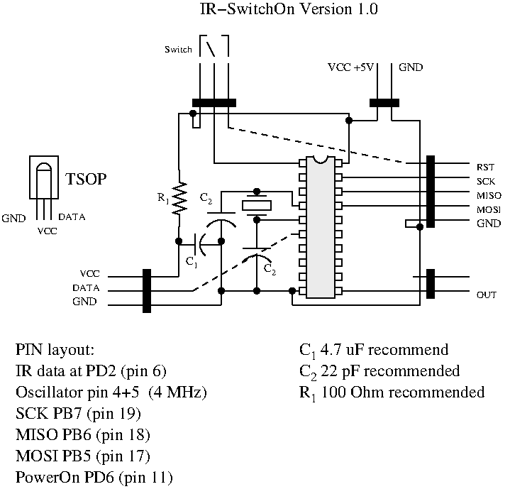
Here is the basic layout of the components:
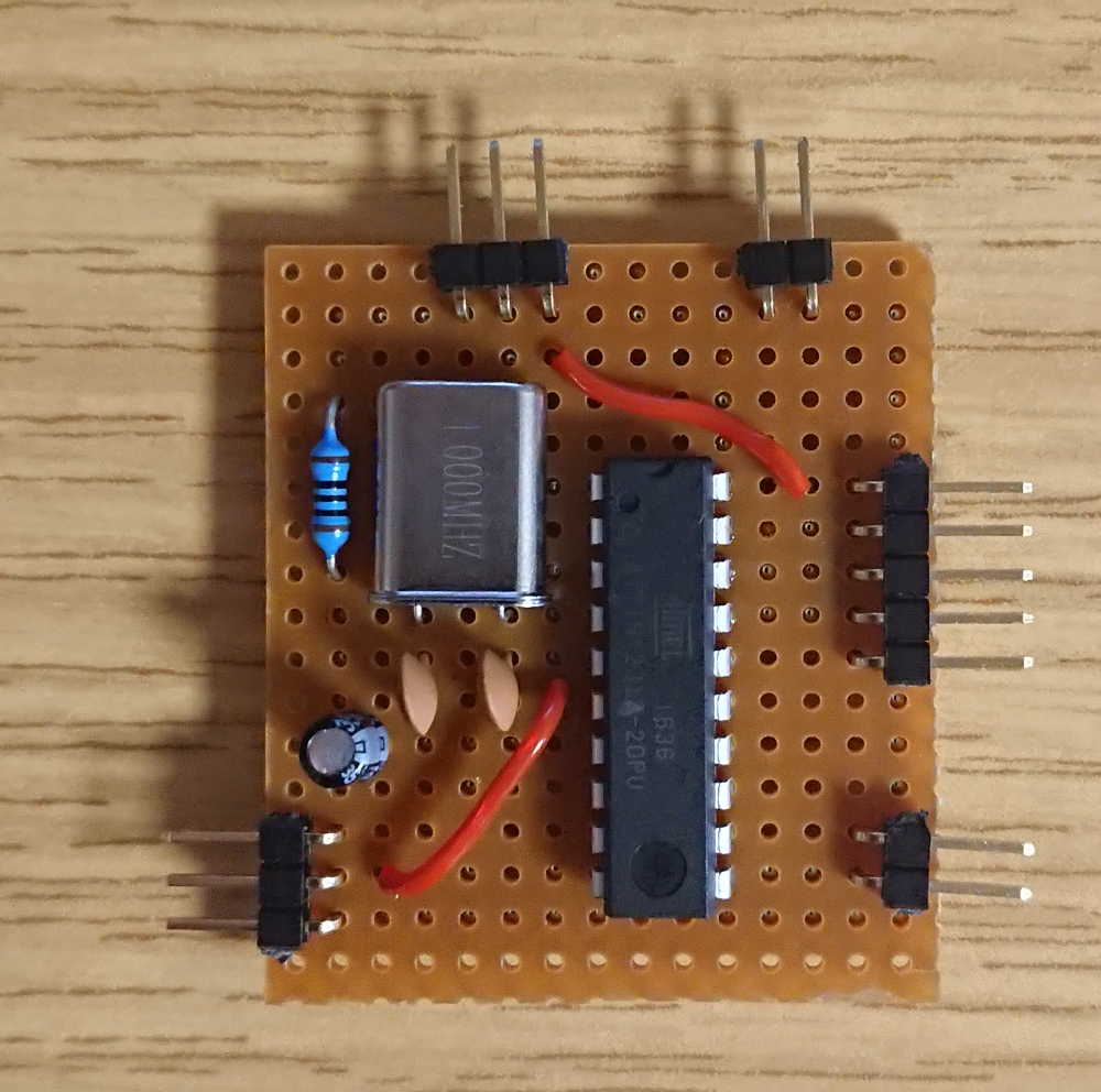
This is the actual board:
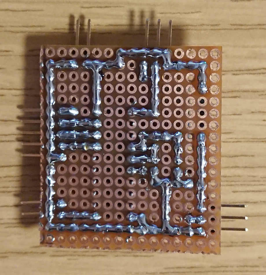
and this is what it looks like on the back:
Be aware that the TSOP connnector uses a different layout than the TSOP itself to make the board design it little easier. On a second thought, it should be doable without any other bridge to route the VCC around the data line but since the TSOP is not connected directly anyway, it does not matter for me.
3.2.2. Programming cable
For flashing the ATtiny I use the software UISP (see below) which supports many interface. I chose the parallel port interface since it is easy to build and I have PC around with that interface. USB-to-parallel adapters should work too, but there are also other options like a RS232 interface.For the parallel port, I needed to connect 6 pins:
- parallel port pin 19+21 is GND
- parallel port pin 1 is SCK at the ATtiny (pin 19)
- parallel port pin 2 is MOSI at the ATtiny (pin 17)
- parallel port pin 11 is MISO at the ATtiny (pin 18)
- parallel port pin 16 is Reset at the ATtiny (pin 1)
4. Software
To deploy software on the microcontroller you basically need 2 things. The C environment (compiler, binutils and libc) and the tool to flash the microcontroller with the binary.4.1. Compiling code
To generate machine code for the ATMEL microcontroller, I use GCC as cross compiler.You need:
First compile the binutils for AVR platform:
$ export PREFIX=$HOME/avr
$ export PATH=$PATH:$PREFIX/bin
$ bunzip2 -c binutils-2.32.tar.bz2 | tar xf -
$ cd binutils-2.32
$ mkdir obj-avr
$ cd obj-avr
$ ../configure --prefix=$PREFIX --target=avr --disable-nls --disable-werror
$ make
$ make install
Then you compile the cross-compiler:
$ bunzip2 -c gcc-4.9.4.tar.bz2 | tar xf -
$ cd gcc-4.9.4
$ mkdir obj-avr
$ cd obj-avr
$ ../configure --prefix=$PREFIX --target=avr --enable-languages=c --disable-nls --disable-libssp --with-dwarf2
$ make
$ make install
And finally the libc:
$ gunzip -c avr-libc-2.0.0.tar.gz | tar xf -
$ cd avr-libc-2.0.0
$ ./configure --prefix=$PREFIX --build=`./config.guess` --host=avr
$ make
$ make install
4.2. Flashing tool
To transfer the actual binaries to the ATMEL microcontroller I use UISP.I needed two patches:
- uisp-20050207-avr2313.patch (1 kB) to support the ATtiny 2313 model
- uisp-20050207-compilefix.patch (0 kB) to fix a compile issue
$ gunzip -c uisp-20050207.tar.gz | tar xf -
$ patch -p0 <uisp-20050207-avr2313.patch
$ patch -p0 <uisp-20050207-compilefix.patch
$ cd uisp-20050207
$ ./configure --prefix=$PREFIX
$ make
$ make install
4.3. Prepare ATtiny fuses
The ATMEL microcontroller uses fuses to configure some hardware parameters.As a very first test whether the device and programming adapter works, you can use UISP to read the current fuses. To do so, put the jumper to the programming position and run the following command:
uisp -dprog=dapa -dlpt=0x378 -v=3 --rd_fuses
- -dprog selects the programming interface (parallel port)
- -dlpt selects the actual parallel port to use (0x378)
If everything works as expected you will see some output, basically 4 different hexadecimal values (low byte, high byte, extended byte, and checksum).
For details about the choices of the fuses, please check the ATtiny manual. Here are the values for my setup:
- CKSEL3-1 need to be 110 for 3-8 MHz
CKSEL3-1 is bit 3-1 in the low byte. - CKSEL0: 1 for crystal oscillator
CKSEL0 is bit 0 in the low byte - SUT1-0 is the startup time, either 01, 10, 11 (should not matter, but I chose 11 to be on the safe side)
SUT1-0 is bit 5-4 in the low byte - BODLEVEL for voltage drop detection, I chose 101 for 2.7V
BODLLEVEL is bit 3-1 in the high byte - CKDIV8: 1 (not dividing the clock)
CKDIV8 is bit 7 in the low byte
So the actual values for the fuses are:
- low byte: 11111101 = 0xfd
- high byte: 11011011 = 0xdb
To set those values:
$ uisp -dprog=dapa -dlpt=0x378 -v=3 --wr_fuse_l=0xfd --wr_fuse_h=0xdb
4.4. First test program
To test whether all components work as expected, I wrote two very simple programs.4.4.1. Simple pin toggle test
This program basically just periodically toggles output pin PB6 (MISO, mapped to parallel port pin 11).This is the sourcecode (0 kB). To compile and install:
$ avr-gcc avr_demo.c -c -o avr_demo.o -Os -g -mmcu=attiny2313
$ avr-gcc avr_demo.o -o avr_demo.elf -mmcu=attiny2313
$ avr-objcopy -j .text -j .data -O ihex avr_demo.elf avr_demo.hex
$ uisp -dprog=dapa -dlpt=0x378 --erase --upload if=avr_demo.hex -v=3 --verify
The programm should run directly after flashing, you can leave the jumper at the programming position.
4.4.2. PC verify program
To see the actual pin change, I also wrote a little linux program to read pin 11 of the parallel port (using parapin).You can downlad the tool (239 kB). To build extract and run:
$ make compile_pp all
$ ./inputtest
Whenever the pin value changes, two lines are written with the value, the current timestamp and the relative timestamp. The AVR test programm busy-loops for 10000 iterations which takes 4 cycles each so at 4 MHz it will toggle the pin every 10ms. You should be able to see that in the output. Example output looks like this:
New val 0 @ 1556962992.133203 = 512
  diff: 2034142  --  timer @4 Mhz/256: 31783
New val 1 @ 1556962992.142272 = 513
  diff: 9069  --  timer @4 Mhz/256: 141
4.4.3. IR pass-through test program
Next test is to see that the IR decoder TSOP works. The test program (0 kB) reads the connected data pin of the TSOP and write the value the output pin PB6.You can use the some PC program. When you press a button on any remote control, you should see multiple lines of output, probably like 60-70 value changes. This means that it works as expected.
5. Remote control learning
The next step is to actually learn the remote control button sequence to start the PC by setting the output pin to ground.The main idea is pretty simply and dumb, but it is good enough for the purpose. During learning, I use a timer on the ATtiny to measure the time between rising and falling signal edges from the TSOP. Regardless of the actual encoding scheme, this will give a unique fingerprint of the pressed button. This timing fingerprint is then stored in the final binary and the microcontroller uses a simple state machine to match the fingerprint. If the button is recognized, it will set the output pin to ground to start the computer.
Here is a sample output of a LIRC helper tool to visualize the IR data:
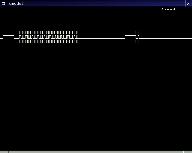
You can see at the beginning a very long high value followed by a shorted low frame. Then the actual bits are transfered using very small delays for a zero bit and a slightly longer delay for one bits. There a different encodings so the signals from another remote control will probably look different but the main concept is the same.
The learning AVR program (1 kB) works as follows:
- first it waits until the input pin from the TSOP changes.
- the timer value is read.
- if the value is larger than a minimum value it will uses for consideration.
- if the value is smaller than a maximum value, it will be stored in a temporary array.
- if the value is larger than the maximum, the whole temporary array is written to the output in a simple bit-encoded format. The format is not efficient but allows to resync at any given point. Any other method is just not worth the effort.
- then the array is cleared and the whole process is executed again.
- a special linux program decodes the data and prints the values.
First step is to identify the maximum value to trigger the data dump. Use the IR passthrough program to measure the time between edges. The very first output will probably show very large relative values as it will be the time to the previous last button press. All consecutive values should be rather similar. For instance for my remote control and the 4 MHz clock, the values will be between 4 and 12 except for the two initial values which are often much longer and something around 180 for my remote control. So 256 is a good trigger value which is used in the learner program. Of course this means that you have to press the button twice to actually trigger the output of the measurement values of the first button press.
To decode the values, use the linux program (239 kB). It basically reads the AVR pin values, tries to resync if necessary, and writes all values one after another. It should be easy to see a unique pattern for each button.
6. Integration
The final program (1 kB) will use the values found by the previous step to put them into an array. Then the microcontroller checks each time difference to match the values in the array. It uses a state machine and checks the first two values separately since they are special start identifier values.If the complete chain of values is matched, it will pull the output pin to ground for some milliseconds to start the computer.
Since the device basically simulates the press of the power button anytime the IR button is detected, it can be used to power down the PC again. If this is behavior is unwanted you can change the linux configuration to ignore the ACPI event of the power button.
If everything works as expected, you can remove the programming cable, put the jumper at the right position so reset is always high.
7. Possible code changes
Some changes may be necessary if some hardware parameter are changed.If the clock is less than 4 MHz, the timer divider 256 may be to large to measure the time between edges. In this case I recommend to lower then clock divider to 64. But in this case the new values might be too large to fit into an 8 bit array. There should be enough space to use 16 bit arrays, but you can also shift the values by one bit to get an actual timer divider of 128.
8. Final thoughts
This implementation is very simple and does not use any advanced features of the microcontroller. A lot of power can be saved when using an interrupt based measurement so the device sleeps as much as possible. Also, actual decoding of the infrared encoding scheme would make it easier to change the button code. But both aspects weren't important for me. Power consumption is low anyway and more complex code just takes longer to implement and the outcome would basically the same.The hardware design can be simplified too. If you use a separate development board, the final board does not have to have an SPI interface and a jumper. You basically only need VCC, TSOP connection and the output pin. You can also use a smaller oscillator to save some more space. Finally, you can also try to remove all the capacitors and the resistor. The larger capacitor and the resistor is only needed to smooth VCC, but in standby mode it should not be that noisy anyway. The two smaller capacitors are for the oscillator, but it probably works without them too.